
I am working on designing a mobile solar system for our RV conversion. I finally have most of the parts and pieces either here or on the way, so it's time to start thinking hard about what this is actually going to look like. The system is based around four 12V, 100Ah LiFePo4 batteries and a 3.6kW hybrid inverter/charger. This contains an inverter, charger, and solar controller, and also functions as a transfer switch. It's quite a bit smarter than just a transfer switch, and can control where power from the solar panels goes based on AC input and AC load. But though it is a smart device, it might decide to do things that are not very smart, so I might need to bypass it.
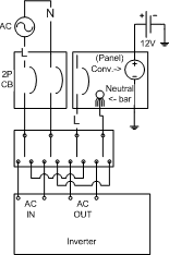
This turned out to be easy and cheap. I am using a DIN rail for power accessory mounting, so I picked out a compatible 4P transfer switch which would mount to it. This is really just four 1P transfer switches: Their inputs can be switched either to one of two contacts, or disconnected by moving the toggle to the center position. What makes it a single thing is that the toggles are linked together so they all switch at once. What I will do is use the "outputs" of the third and fourth switches as inputs. The second output of the first switch will link to the second output (now input) of the third switch, and the second output of the second switch to the second input of the fourth switch. The first output of the first and second switches will go to the AC input of the inverter, while the first input of the third and fourth switches will connect to the AC output of the inverter. When the switches are "on", they will connect AC inlet power (both the hot and neutral of which will pass through a 2P circuit breaker) to the AC input of the inverter, and the AC output of the inverter will be connected to the panel. In the center position, no AC source is connected to anything, and the panel will be safe. The 2P inlet breaker is also switchable, as is the 2P DC breaker which the output from the solar panels comes through. no 12V wiring is pictured here except the chassis battery and the connection from the 12V "Converter" (charger/power supply) which is in the 120VAC panel. In the down position, the transfer switch will connect the output of the inlet power circuit breaker to the panel, cutting the inverter completely out of the AC power system.
The bus has an existing 12 volt system. The converter in the panel's job is to provide 12 volt power when the inverter is running. It is likely that I will need another way to get power from one side to the other. Since it only needs to buck the voltage, this might be a solar controller, as some of them are good at limiting current and can do this job okay. There are also purpose built 24 to 12 volt battery chargers. The converter only provides 12 volt nominal (13.6ish) at 45A, so it wouldn't take much hardware to provide basically the same benefit. The bus battery is currently expected to run some lighting and a diesel heater, and possibly a radio or two. Eventually, there will also be a small compressor; besides the suspension and brakes, the door also runs on air.
Power is stored in two parallel, independently fused, series pairs of 100 Ah LiFePo4 batteries. These have overheat and freeze protection, and can be mounted at any angle. On the ground side they will pass through the shunt of a power monitor, and on the hot side a Blue Sea style big red plastic 1/2/1+2/disconnect switch. This setup allows work to be done on the batteries separately if necessary. At full power, the inverter should draw about 150A from the batteries, which just one pair cannot handle, but they should be able to do around 2/3 output (2400W). The batteries also of course have BMS, which provides protection features and performs internal balancing of their cells.
If the batteries become unbalanced from one another, which is to say charged to different levels, it's important to address this before reconnecting them. You should always fully charge all batteries before connecting them together in series or parallel. The system is also going to include a pair of active equalizers which themselves have a parallel link, which allows all four batteries to be equalized to one another. Small differences in conductivity of cables, connections, or battery cells themselves can cause batteries to take on slightly different states of charge if not equalized. The selector switch will allow connecting either bank for charging. The batteries' manual also states that while their "standard" charging voltage is 14.6, they will tolerate up to 15V for equalization. This is not likely a good idea without temperature monitoring. You can simply buy 24 or 48 volt batteries, which have internal BMS which balances all of the cells individually at once, but I wanted more flexibility. This system could be run with just a couple of flooded car batteries if necessary.
One additional redundancy feature I'm trying to figure out a way to work into the design is power routing for accessories which can run on either 12 or 24 volts. The amount of larger equipment which will do this is quite small, but I'm now seeing a lot of USB chargers and addon lighting modules which will run on either. It would be nice to be able to operate any equipment like that even if the 12 or 24 volt system were out of commission. It would reasonably all have to be on the same home run.
Charging current from the inverter combo is limited to 120A, and the expected charging current is only 20A so this is not necessarily a problematic limitation. However, that could imply that the charging current from the solar panels is limited to 40A, which would be unfortunate as they should be capable of producing enough wattage to push 63 A at the charging voltage. I do have another solar charge controller which will do just about that many amps, but I'm hoping that this one will actually do at least 60 from the solar alone. 4200W/60V (minimum charging voltage) is 70A, so that represents a reasonable maximum possibility.
Another goodie going into the design is a programmable under/overvoltage protection relay. In RVing this is commonly done with a moderately expensive device called a watchdog, but you can get a little box that sits on a DIN rail and does the same job for around ten dollars. It also displays voltage and current in the bargain. I'm putting one between the inlet breaker and the transfer switch, and an only slightly cheaper voltage and current meter between the other side of the transfer switch and the 120 volt panel so that I can see with a glance at the rail what is happening in both directions, and the individual battery voltages.
While neutrals will be broken and switched with hot leads for safety, the last nifty feature of the DIN rail comes into play when talking about the ground conductor. Instead of connecting a hot bar to the back of the breaker like a residential panel does, the rail carries the ground. Items are clipped onto the rail and not just slid on, and modules which need ground can get it by being clipped to the rail, while grounding lugs used to attach grounding wires are also grounded through their clip. DIN rail is also commonly used for factory automation, utilities control and monitoring and such, so there are all sorts of sensor and controller modules, relays, and power supplies available. It's likely this system will get reconfigured, and some of the hardware will be moved, and the rail system allows for that.